![]()
|
|
| Calculation (35633) | |
|
|
|
| Home > SubChat | |
[ Post a New Response | Return to the Index ]
| (35633) | |
Calculation |
|
|
Posted by Fulton Frank on Tue Jan 4 12:02:10 2005 Hi, one project I'd like to do between terms now is caculate how high a train's outter wheel climbs up its flange when rounding a curve. For this I'd need: the diameter of a wheel (I believe 32" is correct) and also the outside diameter of the flange. The angle of the flange chamfer is important too although i could estimate it. And finally what is the minimum radius of curvature of the tracks on the system - is this measured to the inside or outside rail (probably a small correction anyway). With all this I think one can get a pretty estimate of the maximum alawable speed is for a given curve. Thanks for your help. |
|
| (35637) | |
Re: Calculation |
|
|
Posted by VictorM on Tue Jan 4 12:30:05 2005, in response to Calculation, posted by Fulton Frank on Tue Jan 4 12:02:10 2005. From what I've seen of flanges they are vertical, with an inner round where they meet the "tread", and a rounded edge at the top. Also on sharp curves there is a guard rail inside the inner rail that presses against the back of the flange on the inner wheel to help keep the wheels on the track. I think the location of the car's center of gravity relative to the track determines the maximum allowable speed on a curve, but I could be wrong. Another interesting thing is that the wheels are rigidly attached to the axle, but since the outer wheel has to travel a greater distance on a curve than the inner wheel, there is some slippage, which explains the "squeal" you often hear. They try to minimize this at the start of some curves by automatically squirting water or grease onto the wheels. The mininum curve radius is (I think) 120 feet for B Division cars and 90 feet for A Division cars. I don't know if it's the inner or outer rail. |
|
| (35660) | |
Re: Calculation |
|
|
Posted by Fulton Frank on Tue Jan 4 13:11:47 2005, in response to Re: Calculation, posted by VictorM on Tue Jan 4 12:30:05 2005. That's preceisly the point, Vic. The rigid axel would cause much slippage if the effective diameter of the inner and outer wheel were the same. But with a beveled flange, the centripital force causes the outer wheel to "ride up" on the bevel. This increases the effective diameter of the outer wheel relative to that of the iner one. Since both wheels have the same angular speed, the larger effective diameter of the outer wheel allows it to cover more length and hence - at one particular speed - not slip at all. Now, obviously if the train's speed is so high that the force is so high that it rides up past the outer diameter of the flange, the train dereails. (that's what the inner guied rail you mentioned is all about preventing). Thanks for the curve radii, but I still need the outter diameter of the wheel...... |
|
| (Sponsored) |
iPhone 6 (4.7 Inch) Premium PU Leather Wallet Case - Red w/ Floral Interior - by Notch-It |
| (35787) | |
Re: Calculation |
|
|
Posted by BIE on Tue Jan 4 21:14:46 2005, in response to Re: Calculation, posted by Fulton Frank on Tue Jan 4 13:11:47 2005. 34 Inches. |
|
| (35790) | |
Re: Calculation |
|
|
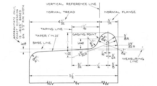
Posted by Jeff H. on Tue Jan 4 21:24:20 2005, in response to Calculation, posted by Fulton Frank on Tue Jan 4 12:02:10 2005. Are you factoring super-elevation in this?The profile of the wheel is quite complicated. Take a look at this scale drawing There are well-established formulae for the allowable speed given the degree of curvature (i.e. radius) and the super-elevation. You'll find the speeds are far less than those which would actually cause a derailment. The radius of curvature is generally referenced to the center line of the track, so add or subtract half the gauge to get the radii of the rails. |
|
| (35801) | |
Re: Calculation |
|
|
Posted by Stepney on Tue Jan 4 22:06:26 2005, in response to Calculation, posted by Fulton Frank on Tue Jan 4 12:02:10 2005. I did a quick layout based on 90 foot radius to track center, and 34 inch diameter wheels. To roll as a cone,(no slippage), the outer wheel should be 1.82 inches larger than the inner wheel. So the flange shown in the picture from Jeff H. would be large enough to maintain guidance. |
|
| (35856) | |
Re: Calculation |
|
|
Posted by Jeff H. on Wed Jan 5 03:46:44 2005, in response to Re: Calculation, posted by Stepney on Tue Jan 4 22:06:26 2005. The issue of train dynamics on a curve is a very complicated one.I assure you, on a 90 foot radius curve, the radius of the point of contact of the outer wheel does not shift by 1.82 inches!!! This would mean the wheel climbs to nearly to end of the flange. There are three ways that wheelsets can steer around a curve: 1) Through the action of the flange and fillet of the inner wheel. 2) Through the action of the guard rail against the outer wheel. 3) Through "coning" Let's start with (3). The typical AAR wheel profile has a tread which is tapered 1-in-20. On very mild curves (one guideline is less than 5 degree, i.e. a radius of approx 1200' or more), the wheelset shifts its point of contact on both rails. The wheels move towards the outside of the curve, so the inner wheel makes contact further out on the tread, where the diameter is slightly smaller, and the outer wheel sees a slightly larger diameter. This coning is sufficient to steer around mild curves with no assistance from the flanges. (1) Clearly the flange, either the rounded fillet between the tread and flange, or the straight diagonal face of the flange itself, can steer the wheelset. However, this sort of action is very destructive to the flange profile and is to be avoided. The tighter the curve, the worse it is on the flange. Flange steering happens at a switch, between the point and the heel. (2) For tight curves, a guard rail is used on the inner rail. This steers the wheelset by a sliding contact against the back face of the flange. Since this surface is not used for traction, the guard rail can be greased heavily, cutting down on flange wear. Unless the guard rail is installed wrong, the flange of the inner wheel never makes contact with the rail, and thus is not worn down. Now, how do we reconcile this with the apparent need to match the linear speed of the two wheels? Undoubtedly you've derived the formula r2/r1=(R+g/2) / (R-g/2), where r2 is the radius of the outer wheel, r1 the inner wheel, R the track curve radius, and g the track gauge. However, in doing so, you've made the assumption that the axle of the wheelset is normal to the rail. Clearly, this can not be, because the two axles of the truck are rigidly held parallel. Can two parallel lines be normal to the same circle? Of course not. The leading axle is pointing "out" of the curve, and the trailing axle is "digging in". So what is actually happening in a sharp curve is that the force exerted by the point of contact of the wheel with the rail is not quite tangent to the curve. There is a radial component as well. That latter force is resisted by the guard rail reaction, which causes the wheelset to pivot (steer) around the contact point. The interface between the wheel tread and the rail is not strictly static friction. In fact, exactly what is happening here is subject to some debate among rail engineers. It is a slip-grip-slide contact and some believe that it oscillates among these states rapidly |
|
| (35923) | |
Re: Calculation |
|
|
Posted by VictorM on Wed Jan 5 11:43:12 2005, in response to Re: Calculation, posted by Jeff H. on Tue Jan 4 21:24:20 2005. Fascinating information! I work for a company that sells CAD/CAM software, including some applications we write in house. It would be a good practice blueprint for our students for a numerical control lathe. Thanks. |
|
| (35936) | |
Re: Calculation |
|
|
Posted by VictorM on Wed Jan 5 12:15:31 2005, in response to Re: Calculation, posted by Jeff H. on Wed Jan 5 03:46:44 2005. More fascinating information! Thanks. I think you meant "outer wheel" in 1) and "inner wheel" in 2). I saw a diagram somewhere that on some European high speed trains the 2 axles of a truck can swivel relative to each other so they always remain perpendicular to the rails on a curve. |
|
| (36166) | |
Re: Calculation |
|
|
Posted by Jeff H. on Wed Jan 5 20:12:19 2005, in response to Re: Calculation, posted by VictorM on Wed Jan 5 12:15:31 2005. Yeah, you're right about the correction.Steerable axle trucks are not a new idea...Brill had the "Radiax" truck nearly 100 years ago. The Bombardier trucks on the R-142s have a limited amount of radial action. Look closely at how the journals are attached to the truck frame using a 3-point connection. |
|
| (36242) | |
Re: Calculation |
|
|
Posted by Fulton Frank on Thu Jan 6 07:57:39 2005, in response to Re: Calculation, posted by Jeff H. on Wed Jan 5 20:12:19 2005. I am truly edified! Yes, Jeff, my starting point would have been the formula you presented. But, I was totally going to forget about the fact of the two rigid axels per truck! Also, earlier, you (or someone) mention "super elevation" does that mean banking?Back to the semi ridigid truck. So that explains the strange look on the R142 jurnals. I always wondered about that design. Final point; what about single axel trucks. Did not some old European freight cars use them? Obviously that's a problem for heavy cars like BMT Standards, but what the newer lighter designs..... |
|
| (36243) | |
Re: Calculation |
|
|
Posted by SelkirkTMO on Thu Jan 6 08:00:33 2005, in response to Re: Calculation, posted by Jeff H. on Wed Jan 5 20:12:19 2005. Jeff, you might be amused to know that on the Bombas, the rubber chevron mounts tend to take quite a beating, but the real nastiness to the design is what happens to the automatic slack adjusters moving on their own on curves. An interesting design indeed. :) |
|
| (36244) | |
Re: Calculation |
|
|
Posted by H.S.Relay on Thu Jan 6 08:11:15 2005, in response to Re: Calculation, posted by Fulton Frank on Thu Jan 6 07:57:39 2005. Superelevation (Banking) is used to increase the "comfort speed" for passengers around curves, but Jeff, you're saying it also comes into play for steering? Because the center of gravity is shifting twoards the inner rail?European frieght wagons do have two axle cars, but they don't use trucks, the axles are attached to the car frame and don't pivot, the car itself becomes one ridgid "truck" and the axles are still not radial. |
|
| (36277) | |
Re: Calculation |
|
|
Posted by Dan Lawrence on Thu Jan 6 10:43:54 2005, in response to Re: Calculation, posted by SelkirkTMO on Thu Jan 6 08:00:33 2005. Interesting.Our ABB LRV's have the rubber chevrons in their trucks, which were touted as "Self-Steering" to reduce rail wear in curves (which we have a lot of, including several 30 foot "flange screamers". What actually happened is that after 10 years of service, a lot of rail had to be replaced since the trucks actually beat the rail to death. The wear was heaviest in the street trackage between Mount Royal and Camden stations. The curves from Mount Royal to Oliver Street had sunk 4 1/2" below the street surface. All the rail on Howard Street was originally laid with a weird concrete and gunnite mix to hold the rail in place. Nobody when the line was being built knew exactly what would happen to the rail when the energy from a stopping car/train would transfer to the rail. During the shutdown during the July 2001 Howard Street Tunnel fire, all the rail was ripped out and new 128 pound rail was laid using standard anchoring fixtures. We will see how the rail behaves in the next 10 years. |
|
| (36284) | |
Re: Calculation |
|
|
Posted by SelkirkTMO on Thu Jan 6 11:01:30 2005, in response to Re: Calculation, posted by Dan Lawrence on Thu Jan 6 10:43:54 2005. I have a buddy who used to post on subtalk a while ago and we've discussed the phenomenon. And that the rails are getting the chit beaten out of them would be no surprise. The BIG problem though as I heard when the cars were new was that in addition to "wobbly wheels" they also had "automatic slack adjusters" which would see the radius change and then bring the shoes in to compensate for it. Of course, once the train was out of the curve, the brakes were now "snow brakes." Heh.I'm sure something's been done about it now, but I've also enjoyed videos of the 142's as they waddle like ducks in and out of stations. Great concept, bad idea. :) |
|
| (36565) | |
Re: Calculation |
|
|
Posted by Jeff H. on Thu Jan 6 20:53:25 2005, in response to Re: Calculation, posted by H.S.Relay on Thu Jan 6 08:11:15 2005. Sorry, there's some physics and math in advance of this sentence:When the car is rounding a curve, its inertia wants to take it in a direction tangent to the curve. The "steering" force is normal to the curve, and is pushing the car towards the inside of the curve. From the standpoint of a stationary observer, the car is accelerating radially, towards the center of the curve, and the magnitude of the acceleration is v**2/r. To an observer within the non-inertial reference frame of the car (i.e. a passenger ^H^H^H^H^H^H^H^H customer) that translates to a phantom "centripetal force" of m*v**2/r, where m is the mass of the person. The effect of super-elevation is to change the direction in which gravity acts relative to the person's reference frame. It introduces a force of m*g*sin(x), where g is the gravitational constant (32 ft/s/s or 9.8m/s/s) and x is the angle of super-elevation. This reduces the feeling of being thrown towards the outside of the curve as perceived by the moving observer (who is actually accelerating towards the inside of the curve). The stationary observer sees that the component of gravity acting in the radial direction is M*g*sin(x) and that force is acting to drag the car towards the inside of the curve. (M being the mass of the car). This reduces the total radial force which the track must exert on the car. When g*sin(x)=v**2/r, the force of gravity provides 100% of the steering and there is no thrust on the track and no perceptible sense of being thrown observed by the passenger. We can simplify using the small angle approximation and say that E=56.5*sin(x), where E is the super-elevation of the outer rail above the inner, in inches (56.5 being the track gauge, YMMV in Pennsylvania). Then we get the formula: E=(56.5/32)*(v**2/r) with v in ft/s and r the radius in feet. Sample calculation: At 30MPH (45fps), a 400 foot radius curve would require 8.9 inches of super-elevation to be balanced. This is considered an excessive number, as 8 inches is generally the most lift that one would want to attempt. Therefore, a lower speed limit would be recommended. At 20MPH, the required super-elevation would be only 3.9" |
|
| (36577) | |
Re: Calculation |
|
|
Posted by Fulton Frank on Thu Jan 6 21:09:50 2005, in response to Re: Calculation, posted by Jeff H. on Thu Jan 6 20:53:25 2005. A+ from this physics professor Jeff! (and I don't give many A's!). Not only is the rail fan stuff correct and edifying to many here - I hope, but your correct understanding of centripital acceleration is spot on. As physics profs. we see much confusion over the true nature of centripital force. My compliments. |
|
| (36581) | |
Re: Calculation Superelevation Tables AND TRACK BIBLE |
|
|
Posted by BIE on Thu Jan 6 21:12:49 2005, in response to Re: Calculation, posted by H.S.Relay on Thu Jan 6 08:11:15 2005. Go to Page 3 of this PDF:http://www.usace.army.mil/inet/usace-docs/armytm/tm5-628/chap12.pdf The Table of Contents for this document (Army TM 5-628 Railroad Track Standards) is here: http://www.usace.army.mil/inet/usace-docs/armytm/tm5-628/ |
|
| (36613) | |
Re: Calculation |
|
|
Posted by Fred G on Thu Jan 6 21:54:11 2005, in response to Re: Calculation, posted by Jeff H. on Thu Jan 6 20:53:25 2005. Are these circular curves or are they spirals?Your pal, Fred |
|
| (36688) | |
Re: Calculation |
|
|
Posted by Jeff H. on Fri Jan 7 01:32:22 2005, in response to Re: Calculation, posted by Fulton Frank on Thu Jan 6 21:09:50 2005. You're a physics professor? For some reason I thought you werea college student. |
|
| (36695) | |
Re: Calculation |
|
|
Posted by Jeff H. on Fri Jan 7 01:56:48 2005, in response to Re: Calculation, posted by Fred G on Thu Jan 6 21:54:11 2005. A spiral is a gradual introduction to a curve.Let's say you need to make a right-angle turn around a street corner and the available right of way limits the turn radius to 200 feet. A simple curve has an abrupt transition from tangent (straight) track to an arc with radius 200. Another way of saying this is a 28 degree curve, i.e. for every 100 feet along the curve, the angle changes 28 degrees. An example of a spiral would be the Searles spiral, in which that deflection of 28 degrees would be broken up into 10 segments. At each segement, the deflection would increase 2.8 degrees. So, at the beginning of the spiral, it would be a 2.8 degree curve, then a 4.6 degree curve, etc. One of the effects of a spiral is that the main curve radius needs to be tightened to get the track to wind up in the same place as it was with a simple curve. With regard to super-elevation, the amount of lift corresponds to where in the spiral you are. I.e. the lift gradually increases from 0 to the value appropriate for the main curve. Spirals do not increase the ultimate speed of the curve, but they do reduce the lurch. |
|
| (36743) | |
Re: Calculation |
|
|
Posted by Fulton Frank on Fri Jan 7 07:47:43 2005, in response to Re: Calculation, posted by Jeff H. on Fri Jan 7 01:32:22 2005. at 53, I'd be a pretty dense student!!! |
|
| (36853) | |
Re: Calculation |
|
|
Posted by VictorM on Fri Jan 7 15:05:10 2005, in response to Re: Calculation, posted by Jeff H. on Thu Jan 6 20:53:25 2005. Sorry to disagree with your analysis, but sin(x) should be replaced with tan(x) in your formulas. On a perfectly banked curve there is only a force normal to the track acting on the train, so the train (and its passengers) feel no sideways force. This normal force (call it N) can resolved into two components: N*cos(x) balancing the force of gravity (m*g) and N*sin(x) providing the centripetal force (m*v**2/r). Therefore:N*sin(x)=m*v**2/r, and N*cos(x)=m*g Dividing these two equations gives us tan(x)=v**2/(r*g) Your formula for E is correct: E=56.5*sin(x) Since, for small x, the sine and the tangent are almost equal, your final formula, E=(56*5/g)*(v**2/r), is a good approximation. |
|
| (36993) | |
Re: Calculation |
|
|
Posted by Jeff H. on Sat Jan 8 01:35:34 2005, in response to Re: Calculation, posted by VictorM on Fri Jan 7 15:05:10 2005. I'm glad there are at least two other people who are interestedin this topic! I did all that in my head without the assistance of pencil and paper, so I went back to re-check. I was balancing forces in a line parallel to the axles. Now that I think about it, that is not the direction of centripetal acceleration. The train is moving in a plane which is level, i.e. normal to gravity, not a plane which is parallel to the super-elevated axle. Only a component acts parallel to the track. I should have realized that because in the limit, if the track were tilted 90 degrees, obviously none of the centripetal force would be acting parallel to the track! So, in that case, balancing along the line of the axle, centripetal "force" is cos(x)*m*g*v**2/r, the force is gravity is sin(x)*m*g, solving tan(x)=v**2/(r*g), which is what you got by solving in the other direction (normal to the track). |
|
| (37002) | |
Re: Calculation |
|
|
Posted by Fred G on Sat Jan 8 05:16:56 2005, in response to Re: Calculation, posted by Fulton Frank on Fri Jan 7 07:47:43 2005. Or a lifer!!Your pal, Fred |
|
| (37003) | |
Re: Calculation |
|
|
Posted by Fred G on Sat Jan 8 05:21:14 2005, in response to Re: Calculation, posted by Jeff H. on Fri Jan 7 01:56:48 2005. Right, I remember the card for laying out the spiral section of track, divided into 10 parts. Much easier than doing that calculation on the hood of the truck ;PYour pal, Fred |
|
